Engine assembling Volvo B18 and Volvo B20 |
|
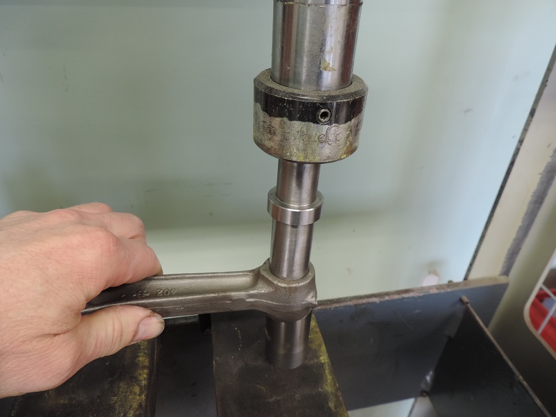
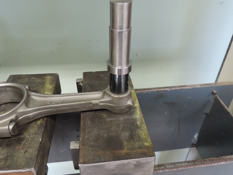
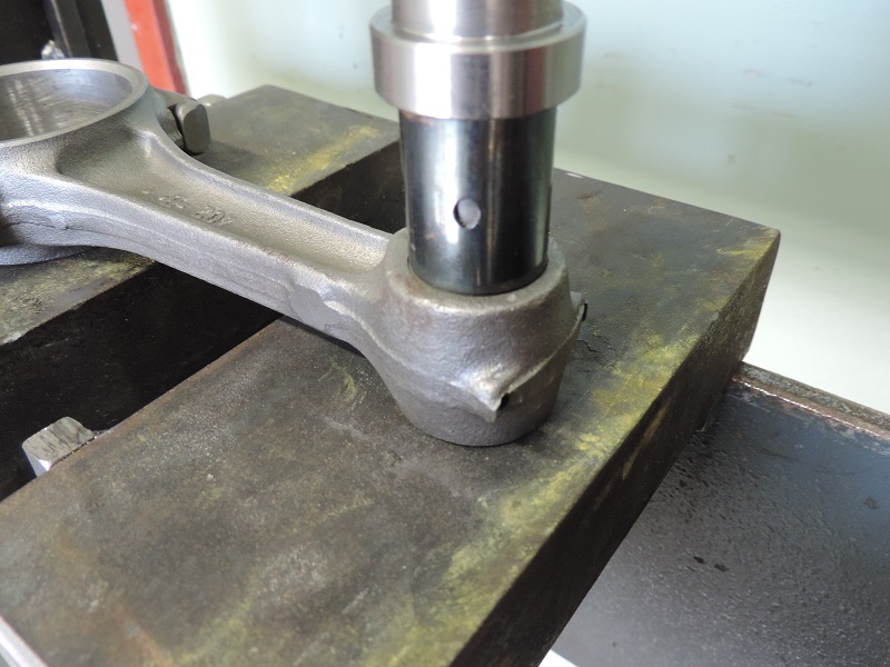
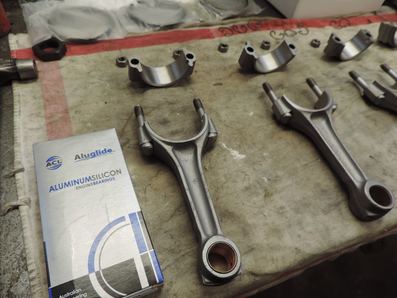
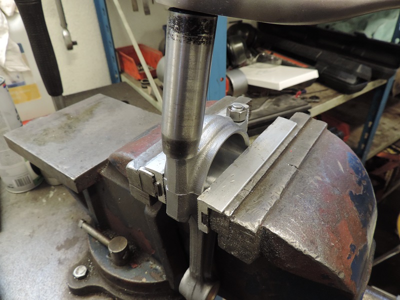
New bushings (p/n 418295) have been installed in the small end. |
Som special tools are required to remove and install these bushings. |
Once installed, the bushings needs to be reamed to the proper size. This procedure, along with honing the large end, is best done at a proper engine shop. |
Step 1 |
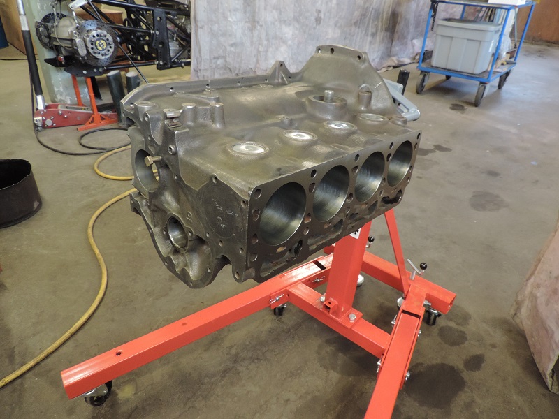
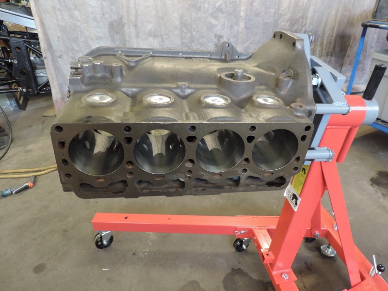
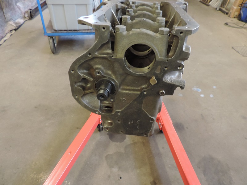
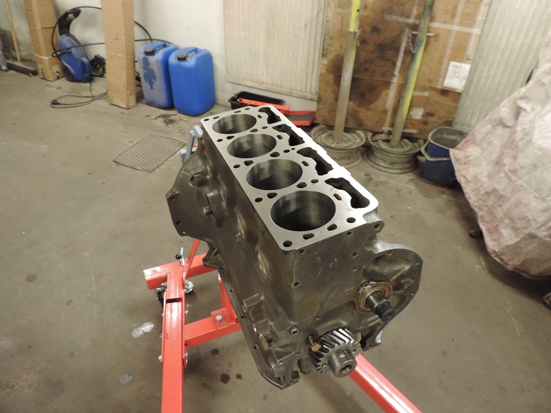
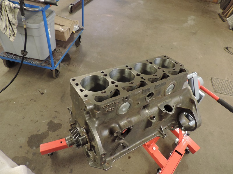
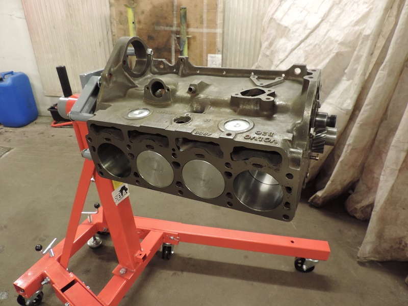
First step is cleaning the block and all its channels properly to remove any debris or granule left from the machining of the block. |
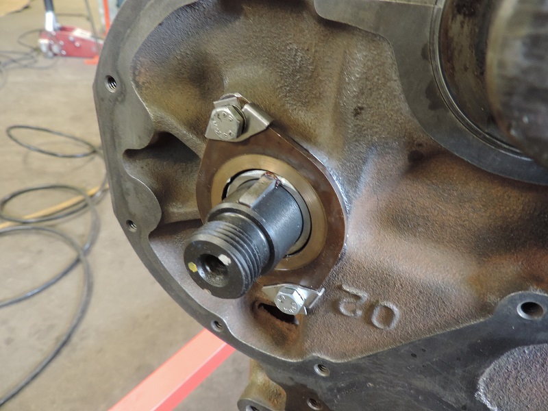
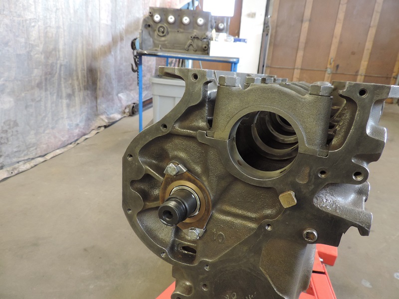
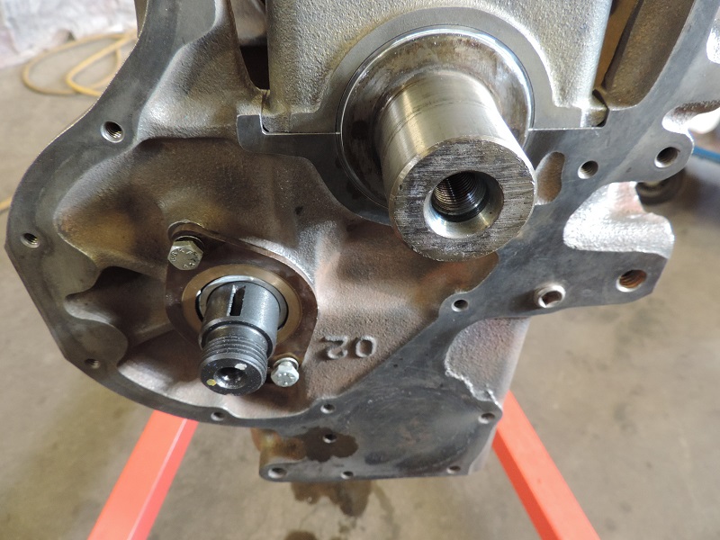
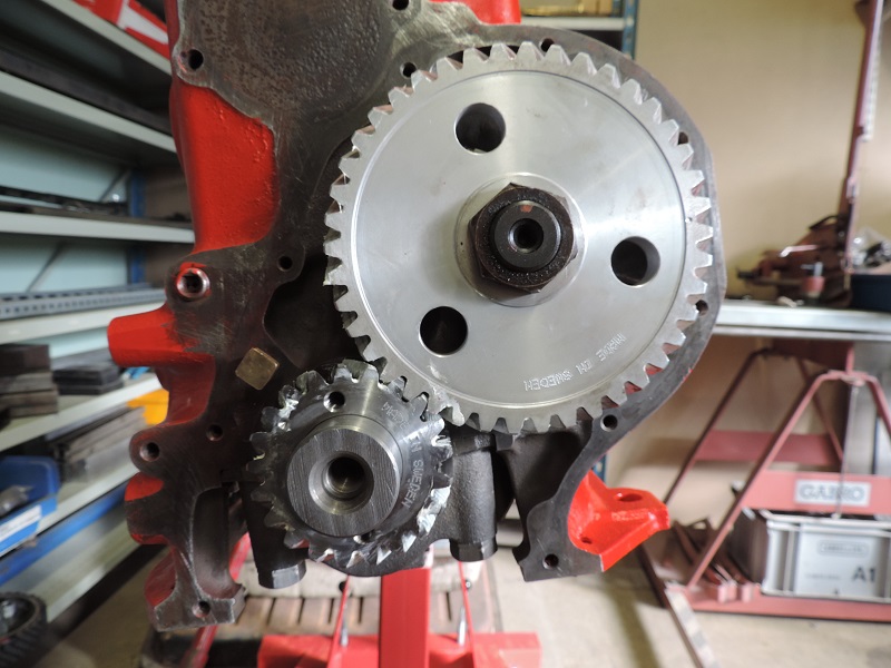
Clean and install fitting, art.nr 418416, which lubes the timing gears. |
Step 2 |
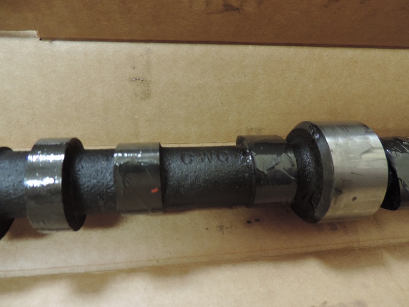
Several grinds are available. From these ones we built, two were equipped with A-cam, p/n 460490, the other two with K-cams, p/n 1218581. First, apply molybdene grease to all cam lobes to protect while breaking in the cam. |
The same paste will later be used on the lifters when the time to install those have come. Cam bearings could be lubed at this time as well, with engine oil or assembly grease, art.nr V903. |
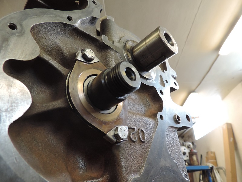
Carefully insert the cam shaft in the engine to avoid damages to the bearings. Once it’s in place, install spacer, p/n 418363, and the thrust flange. Reusing the old flange is usually OK simply by flipping it over as it only wears down on the inside. Assuming of course that this hasn’t already been done in the past. |
When securing the flange, one should always use bolts with lock washer, p/n 418422, or apply a little bit of Loctite adhesive. Never use the lock washers more than once! |
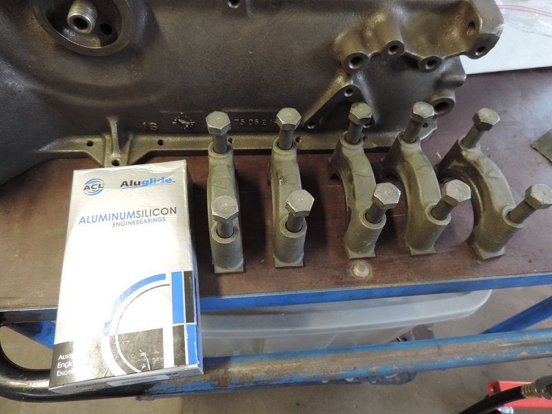
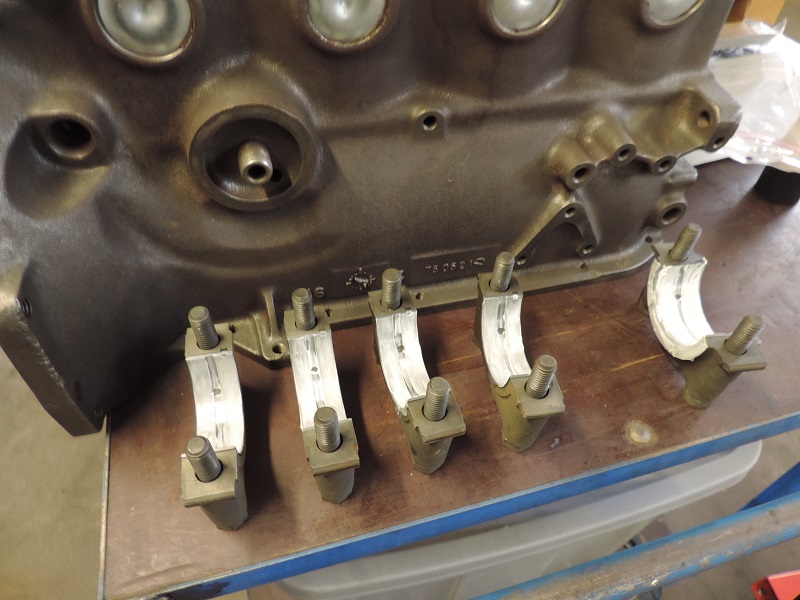
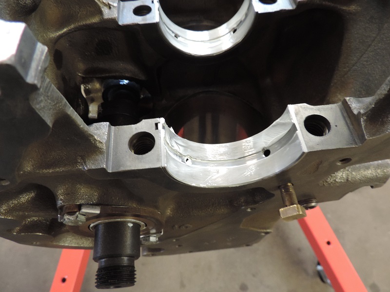
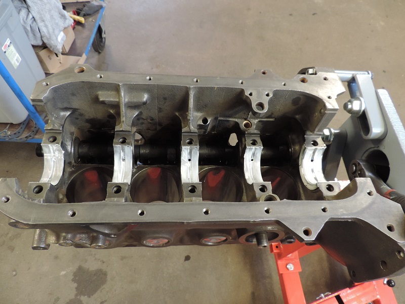
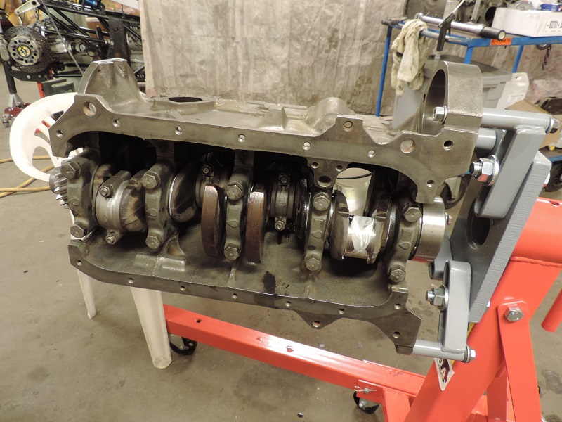
Step 3 |
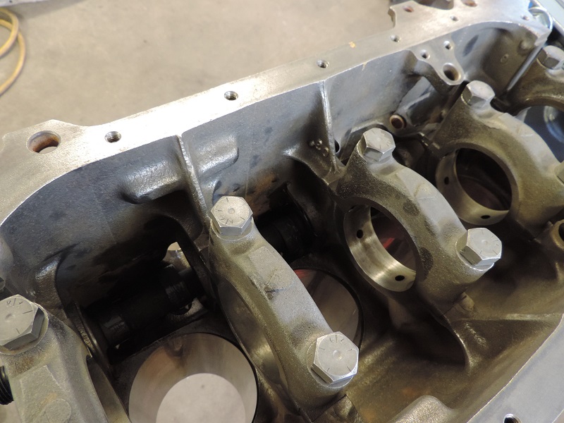
Start by installing the bearings, thereafter apply engine oil or assembly grease to them. |
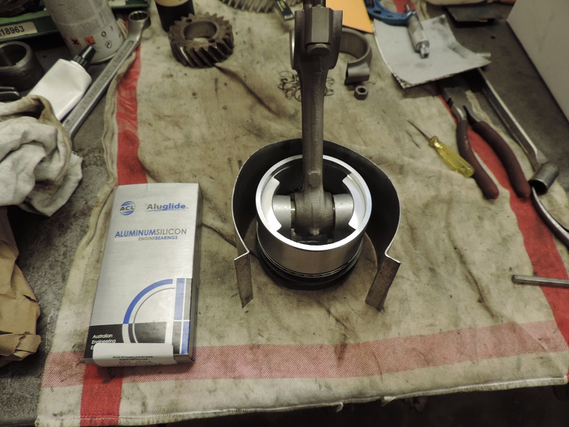
Clean the cups properly before inserting the bearings. We used ACL aluminum bearings, p/n 271215-ACL. |
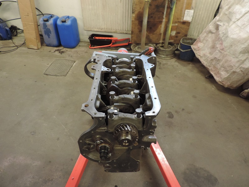
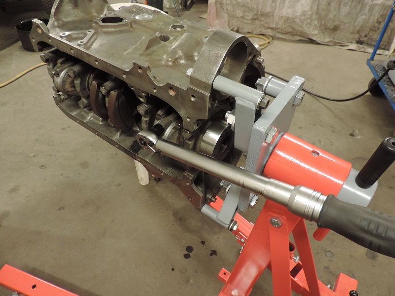
Carefully clean the crank shaft, especially in all oil channels, and then put it in place in the engine. |
Put the caps in place, and tighten them to the specified torque (12-13 Kgm). |
Do this operation in three steps, making sure the crank rotates freely after each tightning. |
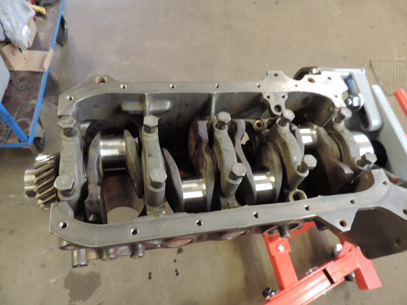
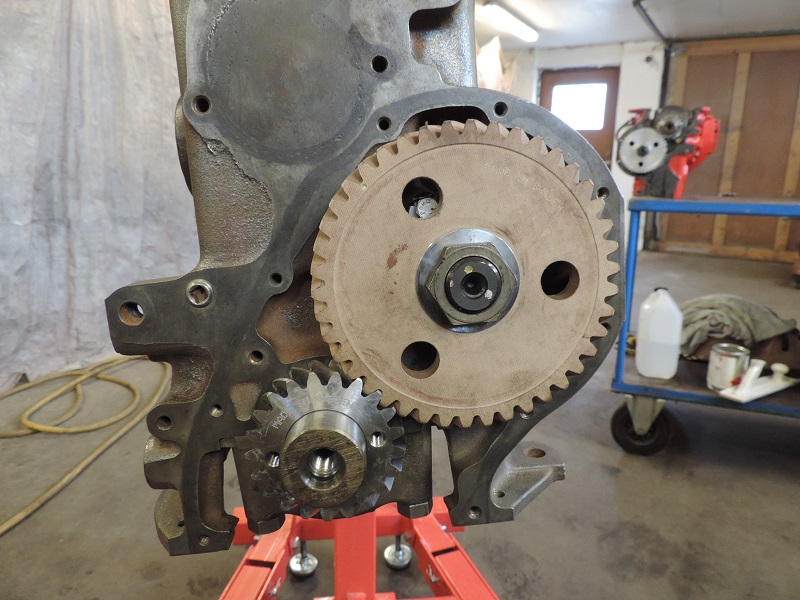
Step 4 |
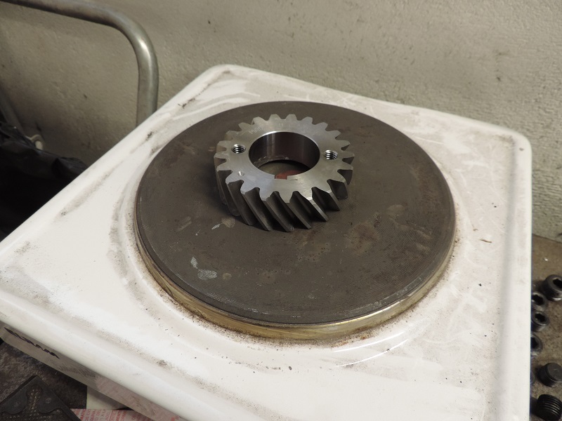
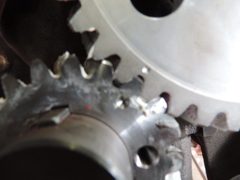
The engines with A-camshaft gets timing gears in fibre/steel, art.nr 270690, and the two engines with K-cam gets timing gears in aluminum/steel p/n 270690AL. |
While you heat up the gear you can mount the index key, p/n 910123 and the index key in the camshaft, p/n 910118. When the gear is hot enough, just slide it on to the crank with the marking facing outwards. If it wasn’t hot enough you might have to use a hammer and carefully hit it to make sure it’s all the way in. NB! Knock carefully! |
|
|
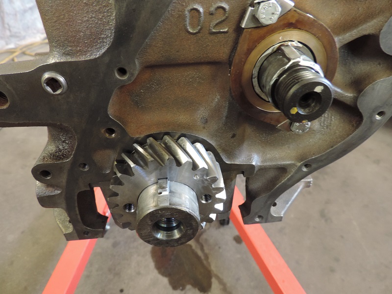
Then it’s time for the cam gear. Also this gear could use some heat but not like the crank gear. Especially if you use the fibre gear. Easiest is to use a hot air gun. |
Mount the cam gear so the marks line up and push it in as far as you can by hand. Then mount the nut p/n 150169 and screw in the gear. |
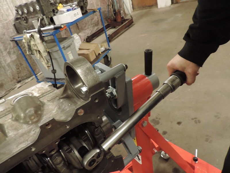
NB! Never use a hammer to mount the cam gear.Finish the job by torque the nut to 13-15 Kgm. Use a plank and put it between the block and crank to avoid the engine from turning over while fastening the nut. |
Step 5 A |
Start with removing the cap from the rod. While these have been machined the cap bolts are torqued and it’s important to fasten them in a proper way while loosening the nuts. This to avoid bending the rod. |
Mount the bearings in their position. |
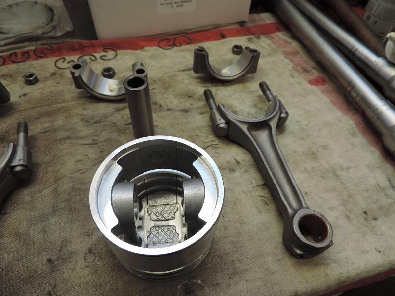
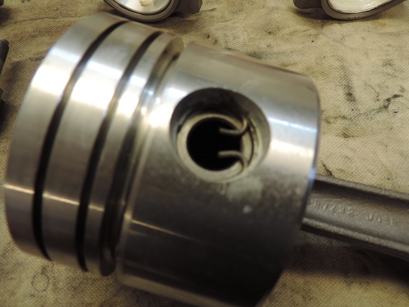
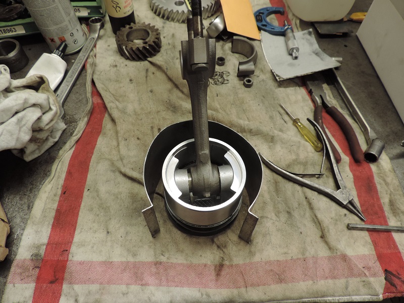
Then it’s time to put oil or assembly lube on the rod bearings, the bushing in the small end of the rod and in the pin hole in the piston. |
Here you have to make sure you do it right. The arrow or mark on the piston should point forward and the number on the side off the big end of the rod should end up at the opposite side of the engine as the cam shaft. Push in the piston pin (an easy push with the thumb should be enough) and then mount the locks. |
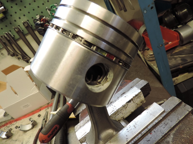
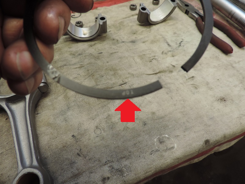
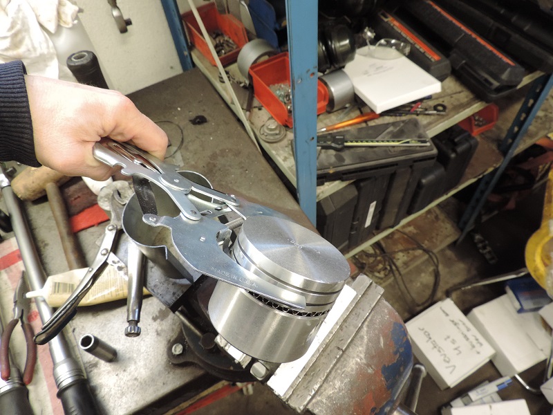
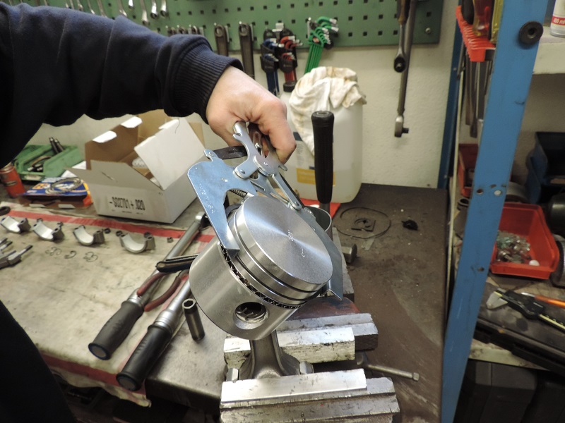
Now it’s time for piston rings! Here it’s important to read the instructions to make sure you mount them with the right side up. Usually there is some kind of marking like a dot or some text that tells wich side should go up. |
For the engine with the A-cam (2 B20) we used cast iron rings art.nr 275336 and the engines with the K-cam got moly rings, art.nr 275283MOLY for the B18 and 275336MOLY for the B20. |
Some rings you can mount either way. |
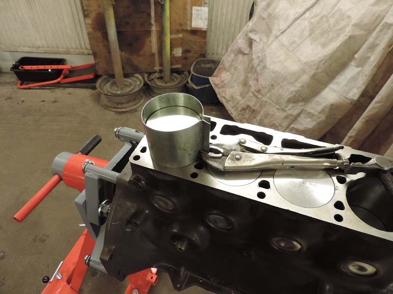
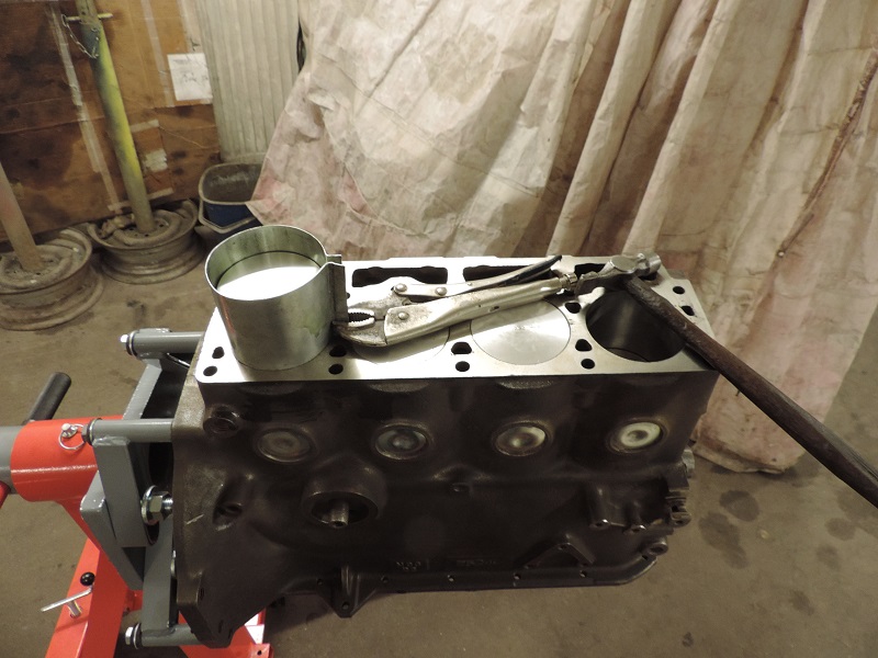
The best is to use piston ring pliers to make the assembly easier and to avoid breaking a piston ring. This tool has art.nr 4234. |
Step 5 B |
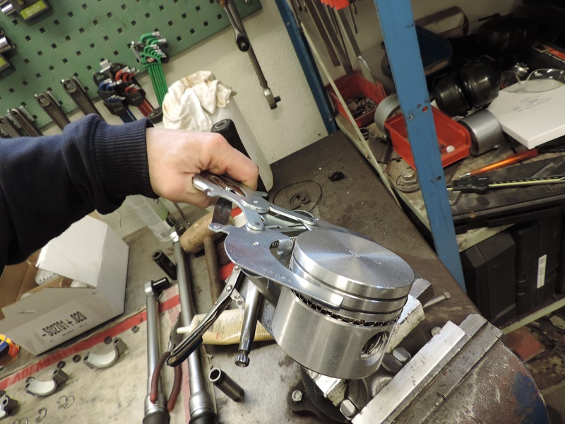
Here you need a tapered ring compressor (best solution!) or some other type of piston ring compressor. |
We used a homemade version made of a 0.8 mm metal sheet and welding pliers. |
Use plenty of oil on both the cylinder walls and inside the piston ring compressor. |
Positioning |
At the same time as you knock down the piston make sure that the big end is off the rod or the rod bolts don’t hit the crank and ruins the journals. |
Then it’s time to steer the piston and rod down in the right cylinder and gently knock it down with a hammer shaft or similar. Make sure to knock gently so you don’t ruin the piston top. You can put a piece of rubber hose on the rod bolts to protect the crank journals from getting nicked. Man kan skydda bultarna med en bit gummislang i lämplig storlek för att undvika att skada vevaxeln. |
When you have pushed the piston all the way down so the rod has bottomed out against the crank it’s time to put on the rod cap and torque it to the right torque (5,2-5,8 Kgm). Start with the number one and four pistons, then turn the crank half a lap and the mount piston number two and three. This way you don’t need to turn the crank around more then necessary. |
Step 6 |
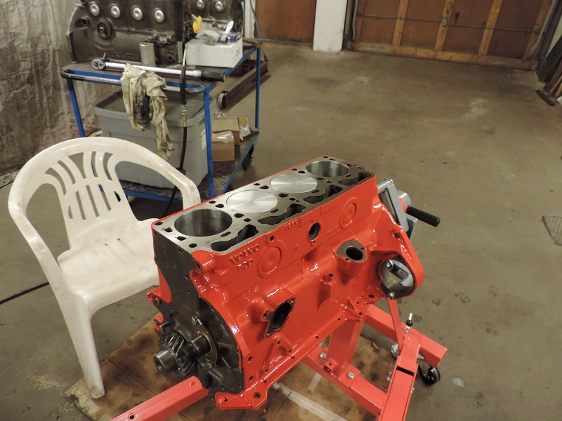
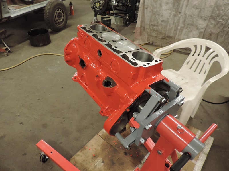
We used Volvo-red engine enamel, art.nr. 9434521. |